![]()
![]()
![]()
|
|
|
||
|
5) Plasma-wall interaction and particles and heat extraction (p 1 - 2 - 3 - 4 - 5 - 6 - 7 )
d) Heat extraction and radiative scenarios
When the plasma particles follow the field lines and intercept the walls in the edge zone, they deposit their energy, which, even if it is much lower than that encountered in the plasma core, is nevertheless formidable for the solid (1 eV , which is the order og magnitude of the strength of energy binding the atoms). In Tore Supra, we may reach heat fluxes of several tens of MW/m2 along field lines, of the same order as those that reign on the surface of the sun (environ 70 MW/m2). To give an idea of the order of magnitude, 10 MW/m2 falling in 1 second on a simple, not cooled graphite-type carbon surface result in a temperature increase of 1000 °C: we might as well say that nothing can stand up to those conditions !
A first idea to lighten the thermal load is to optimise the plasma facing component geometry so as to intercept field lines at a low-angled incidence and spread the incidental flux over as wide a surface as possible. For example, intercepting a field line at an angle of 10° instead of 90° (normal incidence, most constraining situation) attenuates the thermal load by a factor of 6.
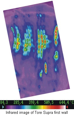
In Tore Supra, a machine intended to operate with long pulses, very particular care has been taken in the design of plasma facing components, which are cooled by a pressurized water flow to be able to withstand intense heat loads for long durations. How are these components designed? Several criteria come into play. First of all, the material facing the plasma. It must withstand thermal shocks, evacuate heat correctly, and not pollute the plasma too much if it is eroded. Carbon, tungsten or beryllium are all suitable candidates. Then, there is the structural material, on which the plasma facing material is assembled and which provides cooling. Here it is heat evacuation that is important, and we usually choose grades of copper in which the cooling pipes are made and in which the water flows under pressure. All that remains is to optimise the thickness of the plasma facing material. If we want to minimise the temperature rise in the component, we must choose the thinnest possible, so that the heat is conducted away as rapidly as possible into the structural material. On the other hand, there must still be a certain solidity, and durability sufficient to withstand erosion by the plasma. Practically speaking, we come to a compromise around a thickness of 1 cm. Progress in the materials used (carbon fibre composite or CFC type, also used in the space industry) and cooling circuit techniques have enabled the development of components capable of withstanding 10 MW/m2 in continuous operation. Tore Supra is an ideal test bench for the technologies and materials developed for the next generation machine (the power injected in the plasma is not as great but falls on a smaller surface as the machine is smaller: the heat fluxes at stake are comparable).
Once the plasma facing component geometry has been optimised, a second idea is to
act on the plasma to reduce the heat load: this is what is being researched with radiative scenarios
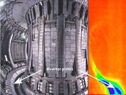
Let us look, for instance, at the orders of magnitude on ITER, the next generation tokamak. There are 300 MW from the plasma core to be evacuated (power produced by the fusion reactions and carried by the alpha particles added to the external power coupled to the plasma). Out of these 300 MW, 100 MW are radiated to the plasma core by different processes (Bremsstrahlung and synchrotron radiation). There are only 200 MW eft which reach the plasma edge, and would be concentrated on the divertor plates, which represent a surface of approximately 10 m² : without radiation, that would give 20 MW/m². Based on studies carried out in the existing machines, radiative scenarios applied to ITER radiate around 150 MW, leaving 50 MW for the divertor (or 5 MW/m², acceptable from a technological point of view) and resulting in heat fluxes of 0.5 MW/m² on the whole machine wall. |
|