Full screen / Default size  Home

Previous page Bottom Next page

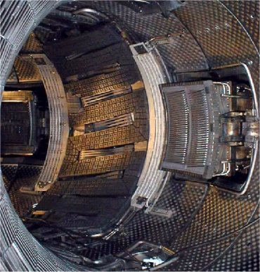
5) Plasma-wall interaction and particles and heat extraction   (p  1 - 2 - 3 - 4 - 5 - 6 - 7 )

How to prevent the plasma and the wall from causing each other mutual damage ? Physicists have developed several configurations to keep the central plasma away from the plasma-wall interaction region.


c) The different edge plasma configurations 

After optimisation of materials, a second idea was to push away the zone where plasma-wall interaction takes place, so as to avoid that impurities emitted in this zone reach the discharge core: this is the axisymetric divertor configuration, where the LCMF is no longer defined by the point of contact with a solid, as in the case of the limiter configuration, but by a "magnetic" frontier created by adding a coil around the tokamak. 

We can see the advantage of the system on the figure below. The flow of particles leaving the plasma by radial diffusion is represented by the large white arrow with a red outline. In the first configuration, on the left, particles follow the field lines and meet the limiter (red arrow 1). These then neutralise, and may, on impact, tear impurities away from the wall, also in the form of neutrals. These neutral particles are not forced to follow the field lines (green arrow 2) and freely flow until they are again ionised by the plasma. Given the proximity of the central plasma, they are very likely to ionise again in the central plasma (red arrow 3). On the other hand, in the divertor configuration, on the right, the flow leaving the plasma is guided by following the field lines towards neutralisation plates far from the central plasma. The impurities are thus more likely to be ionised again in the edge zone, where they follow the field lines, to be once again intercepted by the neutralisation plates. They then remain in closed circuit without interfering with the central plasma: we then talk in terms of impurities screening. It is while testing this new configuration that the improved confinement H mode was discovered on the German machine Asdex during the eighties, which definitively ensured the success of this system. The largest present machines, like JET JET website and JT60-U, are fitted with this type of device.


Ergodic divetor module inside the Tore Supra vacuum vessel

On Tore Supra, we have tested a variant of this configuration, the ergodic divertor, whose basic idea is the same – keep the plasma-wall interaction zone away from the central plasma – but using, to achieve this, a magnetic perturbation which "ergodises" the field lines at the edge of the machine, i.e. instead of a well-organised structure of stacked up tore, we obtain at the edge a chaotic mixture of field lines. The plasma-wall interaction is not kept away "geographically" but "magnetically" from the central zone. Here we come across the chaos concept, a fundamental domain of research in full expansion, currently very much vogue in physics, but also in weather forecasting or economics.

What does this mysterious animal look like? Like 6 modules placed at regular intervals around the chamber, in which a current is allowed to flow to create the perturbation.


The current creating the perturbation (Idiv) flows in the coils shown in black opposite. The magnetic surfaces react by warping near the ergodic divertor module, and the plasma comes into contact with the divertor at the neutralisers.


We see opposite a schematic representation of field lines (tubes of different colours) in the edge zone in ergodic divertor configuration, whose modules are shown in red. The field lines are mixed up and, by taking the flow diagram of particles described for the other configurations, we see that the neutral particles are very likely to be ionised again on a field line returning to one of the modules, and thus to stay stuck in an edge zone where the perturbation has an effect.


. Previous page Top Next page


© CEA 2001 - All rights reserved