![]()
![]()
![]()
|
|
|
||
|
4) - Heating and current generation (p 1 - 2 - 3 - 4 - 5 - 6 - 7 )
c) heating by radio-frequency wave This heating system uses a fast wave which mainly propagates perpendicularly to the magnetic field surfaces at a frequency near to that of the gyration frequency of one of the ion populations (several tens of MHz , corresponding to wavelengths of a few decimetres). The gyration frequency depends on:
Unfortunately, resonant cyclotron absorption is not possible on a plasma with a single ion component (screening effect). We then resort to a so-called minority ion cyclotron heating scenario, which consists in using a plasma with a majority of deuterium ions and a small percentage of hydrogen ions. We then adjust the frequency on the hydrogen, which has a lower mass than that of deuterium, and the wave is to a great extent absorbed by the hydrogen ions, whose energy increases by several hundred eV on each passage of their trajectory in the resonance zone. They then transmit their energy to electrons by collision, which in turn heat up the deuterium ions. Several variations exist. We can choose to adjust the frequency to a multiple of the ion cyclotron frequency, described as harmonic cyclotron heating. In practice the second harmonic is used. When no ion species is in the minority, we can also use a so-called ion-ion hybrid resonance, where there is wave conversion to heat the electrons, described as heating by conversion mode.
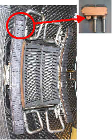
Coupling the wave to the plasma remains a delicate point. The system must be finely adjusted to obtain the correct resonance. The antenna is a bit like the resonant part in an RLC type electric circuit, connecting the power source and the plasma. The plasma density in front of the antenna is critical. If it is too low, the wave cannot pass. The power is then reflected towards the transmitter instead of being transmitted to the plasma, which could be harmful. A security system surveys therefore the operation, and cuts the transmitter power in case of improper coupling. Other complex systems have been developed so that the antenna can adapt to small variations in density (on account of fluctuations linked to turbulence or loss of plasma control). |
|